5 Awesome PN532 NFC Projects: A Complete Arduino Walkthrough With Code

By Modula Industries | Electronics Tutorials
Learn how to use the Modula Industries PN532 NFC Communication Module to read NFC tags, create smart business cards, control electronics wirelessly, log attendance events and build a contactless access-control demonstrator.
Whether you're a beginner exploring Arduino or an electronics enthusiast developing your next embedded project, this guide provides five practical builds, wiring instructions and code you can adapt to your own setup.
Featured product: Modula Industries PN532 NFC Communication Module
Introduction: What Is NFC?
Near-Field Communication (NFC) is a short-range wireless technology that allows compatible devices to exchange information when brought close together. It is used in contactless identification, smart posters, device pairing, access-control systems and many other applications.
At the heart of this tutorial is the Modula Industries PN532 NFC Communication Module, built around the NXP PN532 controller. Operating at 13.56 MHz, it supports several communication interfaces and a range of NFC-related standards, making it a versatile tool for electronics prototyping.
In this guide, we'll build five projects:
NFC tag reader and identifier.
Smart NFC business card.
NFC-activated LED controller.
NFC attendance logger.
NFC access-control demonstrator.
By the end, you'll have a foundation for developing your own NFC-enabled electronics projects.
Meet the Modula Industries PN532 Module
Our PN532 NFC Communication Module offers flexible connectivity for compatible microcontrollers and single-board computers.
Technical specifications
Specification | Details |
Controller IC | NXP PN532 |
Operating frequency | 13.56 MHz |
Communication interfaces | SPI, I²C and UART |
Interface selection | DIP switch |
Supply voltage | 3.3 V DC |
Logic level | 3.3 V |
Stated read range | Up to 5 cm, depending on tag and conditions |
Supported standards | ISO14443A/B, MIFARE, FeliCa and ISO18092 |
Applications | NFC/RFID reading and writing, identification, automation and embedded systems |
The module is available directly from Modula Industries.
What you'll need
For these projects, prepare the following components:
Modula Industries PN532 NFC Communication Module.
Arduino Uno R3, ESP32 or another compatible development board.
Compatible 13.56 MHz NFC tags or cards.
Breadboard and jumper wires.
LEDs and suitable current-limiting resistors.
USB cable and Arduino IDE.
Appropriate voltage regulation and logic-level conversion hardware.
Optional OLED display, RTC module, microSD module and servo.
Not every component is needed for every project.
Important electrical warning
The Modula Industries PN532 module is specified for a 3.3 V supply and 3.3 V logic.
A standard Arduino Uno R3 uses 5 V logic. When connecting the Uno to the module, use suitable bidirectional logic-level conversion on the signal lines and a compatible 3.3 V supply. Never assume that a breakout board accepts 5 V because it can communicate with an Arduino.
Always verify the physical module's pin labels, voltage requirements and DIP-switch configuration before connecting power.
Step 1: Connect the PN532 to an Arduino
For our first project, we'll use I²C because it requires only two data lines.
Configure the PN532's DIP switches for I²C according to the markings or documentation for your specific board.
I²C wiring reference
PN532 module | Arduino Uno R3 |
VCC | Suitable regulated 3.3 V supply |
GND | GND |
SDA | A4/SDA through a compatible level shifter |
SCL | A5/SCL through a compatible level shifter |
IRQ | D2, where required by the library configuration |
RESET | D3, where required by the library configuration |
Connect all grounds together. Verify the level shifter's voltage references and confirm that the module's pull-up resistors are compatible with the selected logic voltage.
ESP32 boards generally use 3.3 V logic, but their exact pin assignments and electrical specifications vary. Check your development board's documentation before wiring.
Step 2: Install the Arduino IDE and PN532 Library
Download the Arduino IDE.
Open the Library Manager.
Search for Adafruit PN532 and install it.
Install any required dependencies, including Adafruit BusIO if prompted.
Select your development board and USB port.
Open the PN532 examples and verify that the interface configuration matches your module.
The Adafruit library supports PN532 communication over I²C and SPI. Its constructor, pin configuration and initialization must match your chosen interface.
Reference: Adafruit PN532 library on GitHub.
Project 1: NFC Tag Reader and Identifier
Difficulty: Beginner
Project overview
Our first build detects a compatible NFC tag and prints its UID (unique identifier) to the Serial Monitor.
This is the foundation for all the projects that follow.
Components
PN532 NFC Communication Module.
Arduino or compatible controller.
Compatible NFC tag or card.
Required wiring and voltage conversion hardware.
Arduino code
Create a new sketch and paste the following code.
#include <Wire.h>
#include <Adafruit_PN532.h>

#define PN532_IRQ   2
#define PN532_RESET 3

Adafruit_PN532 nfc(PN532_IRQ, PN532_RESET);

void setup() {
  Serial.begin(115200);

  nfc.begin();

  uint32_t version = nfc.getFirmwareVersion();

  if (!version) {
    Serial.println("PN532 not detected!");

    while (1) {
      delay(10);
    }
  }

  Serial.println("PN532 detected!");

  nfc.SAMConfig();

  Serial.println("Tap an NFC tag...");
}

void loop() {
  uint8_t uid[7];
  uint8_t uidLength = 0;

  bool found = nfc.readPassiveTargetID(
    PN532_MIFARE_ISO14443A,
    uid,
    &uidLength,
    1000
  );

  if (found) {
    Serial.print("UID: ");

    for (uint8_t i = 0; i < uidLength; i++) {
      if (uid[i] < 0x10) {
        Serial.print("0");
      }

      Serial.print(uid[i], HEX);
      Serial.print(" ");
    }

    Serial.println();
    delay(1000);
  }
}
How it works
nfc.begin() initializes the PN532 library.
getFirmwareVersion() checks whether the module responds.
SAMConfig() configures the reader for tag detection.
readPassiveTargetID() attempts to read a compatible ISO14443A tag.
The for loop prints the UID in hexadecimal.
This code uses the common Adafruit PN532 I²C constructor. Confirm that your IRQ and reset wiring matches the constructor and your module configuration.
Testing your reader
Upload the sketch.
Open Serial Monitor.
Select 115200 baud.
Hold a compatible tag near the antenna.
Check the printed UID.
Example output:
PN532 detected!
Tap an NFC tag...
UID: 04 A1 B2 C3 D4 E5 F6
The UID shown here is illustrative.
What you've learned
You've explored NFC polling, hexadecimal identifiers, library initialization and serial debugging.
Upgrade: Add an OLED display and show a friendly name for each registered tag.
Project 2: Smart NFC Business Card
Difficulty: Beginner to intermediate
Project overview
Create a smart business card that opens your website or digital portfolio when scanned with a compatible smartphone.
Unlike Project 1, this project uses an NDEF URL record. An NDEF record stores structured information, such as a URL, in a compatible NFC tag.
Components
Compatible writable NFC tag.
Smartphone with NFC support.
NFC-writing application.
Optional PN532 module for additional experiments.
Step 1: Write a URL to the tag
The simplest approach is to use a trusted NFC-writing app.
Open the application.
Select the option to create a URL record.
Enter your desired website address.
Write the record to a compatible tag.
Scan the tag with a compatible smartphone.
Verify that the expected URL is presented.
You can create separate tags for a product catalogue, support page, portfolio or contact details.
Step 2: Recognise the business-card tag using Arduino
The following code identifies a registered tag and displays its associated URL in the Serial Monitor. It does not write the URL to the tag.
Add these variables and helper function to Project 1, then replace its loop() function with the one below.
const char* businessCardURL =
  "https://www.modulaindustries.co.za/";

const uint8_t businessCardUID[] = {
  0x04, 0xA1, 0xB2, 0xC3
};

const uint8_t businessCardUIDLength =
  sizeof(businessCardUID);

bool matchesBusinessCard(
  const uint8_t* uid,
  uint8_t uidLength
) {
  if (uidLength != businessCardUIDLength) {
    return false;
  }

  for (uint8_t i = 0; i < uidLength; i++) {
    if (uid[i] != businessCardUID[i]) {
      return false;
    }
  }

  return true;
}

void loop() {
  uint8_t uid[7];
  uint8_t uidLength = 0;

  bool found = nfc.readPassiveTargetID(
    PN532_MIFARE_ISO14443A,
    uid,
    &uidLength,
    1000
  );

  if (found) {
    if (matchesBusinessCard(uid, uidLength)) {
      Serial.println("Business card detected!");
      Serial.println(businessCardURL);
    } else {
      Serial.println("Unknown tag.");
    }

    delay(1000);
  }
}
Before uploading: Replace the example UID bytes with the actual UID printed by your own tag.
What you've learned
You'll have explored NDEF records, URL storage, writable tags and basic tag identification.
Upgrade: Create a collection of branded NFC cards linking to different pages of your website.
Project 3: NFC-Activated LED Controller
Difficulty: Beginner to intermediate
Project overview
Turn an LED on or off by presenting an authorised demonstration tag to the PN532.
This project introduces digital outputs and state management.
Components
PN532 NFC Communication Module.
Arduino or compatible controller.
LED.
220–330 Ω current-limiting resistor.
Breadboard and jumper wires.
Wiring
Connect the LED's anode to digital pin 8 through the current-limiting resistor. Connect its cathode to GND.
Keep the PN532 wiring from Project 1.
Arduino code
Retain the includes, PN532 object and firmware initialization from Project 1.
Add these global variables and helper function, and replace the original loop() function.
const uint8_t LED_PIN = 8;

const uint8_t authorisedUID[] = {
  0x04, 0xA1, 0xB2, 0xC3
};

const uint8_t authorisedUIDLength =
  sizeof(authorisedUID);

bool ledState = false;
unsigned long lastTrigger = 0;

bool isAuthorised(
  const uint8_t* uid,
  uint8_t uidLength
) {
  if (uidLength != authorisedUIDLength) {
    return false;
  }

  for (uint8_t i = 0; i < uidLength; i++) {
    if (uid[i] != authorisedUID[i]) {
      return false;
    }
  }

  return true;
}

void setupProject() {
  pinMode(LED_PIN, OUTPUT);
  digitalWrite(LED_PIN, LOW);
}

void loop() {
  uint8_t uid[7];
  uint8_t uidLength = 0;

  bool found = nfc.readPassiveTargetID(
    PN532_MIFARE_ISO14443A,
    uid,
    &uidLength,
    1000
  );

  if (found && millis() - lastTrigger > 1500) {
    lastTrigger = millis();

    if (isAuthorised(uid, uidLength)) {
      ledState = !ledState;

      digitalWrite(
        LED_PIN,
        ledState ? HIGH : LOW
      );

      Serial.println(
        ledState ? "LED ON" : "LED OFF"
      );
    } else {
      Serial.println("Unknown tag.");
    }
  }
}
Complete the setup
Arduino executes the function named setup(), not setupProject().
Add this line inside the original setup() after the PN532 has been initialized successfully:
setupProject();Replace the sample UID with your actual test tag's UID.
How it works
The code compares the scanned UID with the registered identifier. When the tag matches, the LED state toggles. A cooldown reduces repeated activations.
Upgrade: Control a low-voltage LED strip using a suitably rated driver circuit. Never connect a high-current load directly to a microcontroller pin.
What you've learned
Digital outputs.
Conditional logic.
State management.
Simple event cooldowns.
Project 4: NFC Attendance Logger
Difficulty: Intermediate
Project overview
Create an attendance-logging prototype that records tag scans with timestamps and saves them to a microSD card.
Components
PN532 NFC Communication Module.
Arduino-compatible controller.
DS3231 real-time clock.
Compatible microSD module and card.
Optional OLED display.
Step 1: Install the required library
Install RTClib through the Arduino IDE Library Manager.
The Arduino SD library is available with the standard Arduino platform. This example assumes a DS3231 RTC and a compatible SPI microSD module.
Step 2: Add the logging code
Add the following includes and objects to your existing Project 1 sketch.
#include <SPI.h>
#include <SD.h>
#include <RTClib.h>

const int SD_CS_PIN = 10;

RTC_DS3231 rtc;

bool startLogger() {
  if (!rtc.begin()) {
    Serial.println("RTC not detected.");
    return false;
  }

  if (!SD.begin(SD_CS_PIN)) {
    Serial.println("SD card initialisation failed.");
    return false;
  }

  File file = SD.open(
    "attendance.csv",
    FILE_WRITE
  );

  if (!file) {
    Serial.println("Cannot open log file.");
    return false;
  }

  if (file.size() == 0) {
    file.println("Date,Time,UID");
  }

  file.close();

  Serial.println("Logger ready.");
  return true;
}

void logScan(
  const uint8_t* uid,
  uint8_t uidLength
) {
  DateTime now = rtc.now();

  File file = SD.open(
    "attendance.csv",
    FILE_WRITE
  );

  if (!file) {
    Serial.println("Log write failed.");
    return;
  }

  char timestamp[24];

  snprintf(
    timestamp,
    sizeof(timestamp),
    "%04d-%02d-%02d,%02d:%02d:%02d",
    now.year(),
    now.month(),
    now.day(),
    now.hour(),
    now.minute(),
    now.second()
  );

  file.print(timestamp);
  file.print(",");

  for (uint8_t i = 0; i < uidLength; i++) {
    if (uid[i] < 0x10) {
      file.print("0");
    }

    file.print(uid[i], HEX);
  }

  file.println();
  file.close();

  Serial.println("Scan logged.");
}
Step 3: Integrate the logger
Inside the original setup(), after initializing the PN532, start the logger:
if (!startLogger()) {
  Serial.println("Logger setup failed.");
}
Inside the successful tag-detection branch of loop(), call:
logScan(uid, uidLength);Add a cooldown or tag-removal detection mechanism before calling logScan() again. Otherwise, a tag held near the antenna may generate repeated entries.
Example log output
Date,Time,UID
2026-10-19,09:00:14,04A1B2C3
2026-10-19,09:05:33,04112233
What you've learned
RTC integration.
File handling.
CSV logging.
Peripheral coordination.
Data organisation.
Upgrade: Add a registered-user lookup table and show a person's registered alias instead of the raw UID.
Use test identities while developing. For real attendance records, obtain appropriate consent, restrict access and protect stored personal information.
Project 5: NFC Access-Control Demonstrator
Difficulty: Intermediate
Project overview
Build a model-door demonstration that indicates whether a scanned tag is authorised.
A green LED indicates a recognised test tag, while a red LED indicates an unknown tag. You can later add a servo to simulate a door latch.
Components
PN532 NFC Communication Module.
Arduino-compatible controller.
Green and red LEDs.
Suitable current-limiting resistors.
Optional servo and suitable power supply.
Wiring
Connect the green LED to digital pin 7 and the red LED to digital pin 8, each through its own current-limiting resistor. Connect both LED cathodes to GND.
Keep the PN532 wiring from Project 1.
Arduino code
Retain the PN532 initialization from Project 1. Add these global variables and the helper function, then replace the original loop().
const int GREEN_LED = 7;
const int RED_LED = 8;

const uint8_t authorisedUID[] = {
  0x04, 0xA1, 0xB2, 0xC3
};

const uint8_t authorisedUIDLength =
  sizeof(authorisedUID);

bool checkUID(
  const uint8_t* uid,
  uint8_t uidLength
) {
  if (uidLength != authorisedUIDLength) {
    return false;
  }

  for (uint8_t i = 0; i < uidLength; i++) {
    if (uid[i] != authorisedUID[i]) {
      return false;
    }
  }

  return true;
}

void setupAccessDemo() {
  pinMode(GREEN_LED, OUTPUT);
  pinMode(RED_LED, OUTPUT);

  digitalWrite(GREEN_LED, LOW);
  digitalWrite(RED_LED, LOW);
}

void loop() {
  uint8_t uid[7];
  uint8_t uidLength = 0;

  bool found = nfc.readPassiveTargetID(
    PN532_MIFARE_ISO14443A,
    uid,
    &uidLength,
    1000
  );

  if (found) {
    bool authorised = checkUID(uid, uidLength);

    digitalWrite(
      GREEN_LED,
      authorised ? HIGH : LOW
    );

    digitalWrite(
      RED_LED,
      authorised ? LOW : HIGH
    );

    Serial.println(
      authorised ? "ACCESS GRANTED"
                 : "ACCESS DENIED"
    );

    delay(1500);

    digitalWrite(GREEN_LED, LOW);
    digitalWrite(RED_LED, LOW);
  }
}
Complete the setup
Add the following line to the original setup() function after successful PN532 initialization:
setupAccessDemo();Replace the sample UID with the UID of your own demonstration tag.
How it works
When a tag is detected, the controller compares its UID against the registered identifier.
If the UID matches, the green LED turns on.
If the UID does not match, the red LED turns on.
After a short delay, both LEDs switch off.
What you've learned
Access-decision logic.
Conditional statements.
Digital outputs.
Basic state control.
Hardware integration.
Upgrade: Add a keypad, an OLED display and an event logger. You can also use a servo with a suitable power supply to simulate a door latch.
Security warning: This project is an educational demonstration, not a secure access-control system. Some tag UIDs can be copied or emulated. A real security system should use suitable cryptographic credentials, secure key handling and a properly designed access controller. Do not rely on UID-only checks to secure a real door or valuable equipment.
Troubleshooting Common PN532 Problems
Problem | What to check |
PN532 is not detected | Verify DIP switches, interface configuration, wiring, power and logic levels. |
No tag is detected | Check that the tag uses a supported protocol and position it near the antenna. |
LED activates repeatedly | Add a cooldown or wait for the tag to leave the reader's field. |
NDEF data cannot be read | UID reading and NDEF reading are different operations. Use an NDEF-capable tool or library. |
Writing to a tag fails | Verify that the tag is writable, has enough memory and is not protected. |
SD logging fails | Check the card, SPI connections, chip-select pin and power supply. |
Arduino resets unexpectedly | Inspect voltage levels, grounding, wiring shorts and peripheral power requirements. |
For further technical details, consult the Adafruit PN532 library documentation and the NXP PN532 documentation.
Final Thoughts
The Modula Industries PN532 NFC Communication Module is a versatile platform for exploring contactless communication, embedded programming and electronics prototyping.
Start with a simple tag reader, move on to smart NFC cards, and then experiment with LED control, data logging and access-control demonstrations. Each project introduces skills that you can apply to more advanced Arduino, ESP32 and IoT systems.
Whether you're learning electronics or developing your next prototype, NFC offers an exciting way to connect the physical and digital worlds.
Ready to start building?
Get your module directly from Modula Industries:
Modula Industries — Powering Electronics.
SEO Details
SEO title: 5 PN532 NFC Projects with Arduino Code | Modula Industries
Focus keyphrase: PN532 NFC projects
Meta description: Build 5 PN532 NFC projects with Arduino code, including tag reading, smart business cards, LED control, attendance logging and access-control prototypes.
Suggested URL slug: pn532-nfc-projects-arduino-guide
Blog category: Electronics Tutorials
Suggested tags: PN532, NFC, RFID, Arduino, ESP32, Embedded Systems, DIY Electronics, Electronics Projects
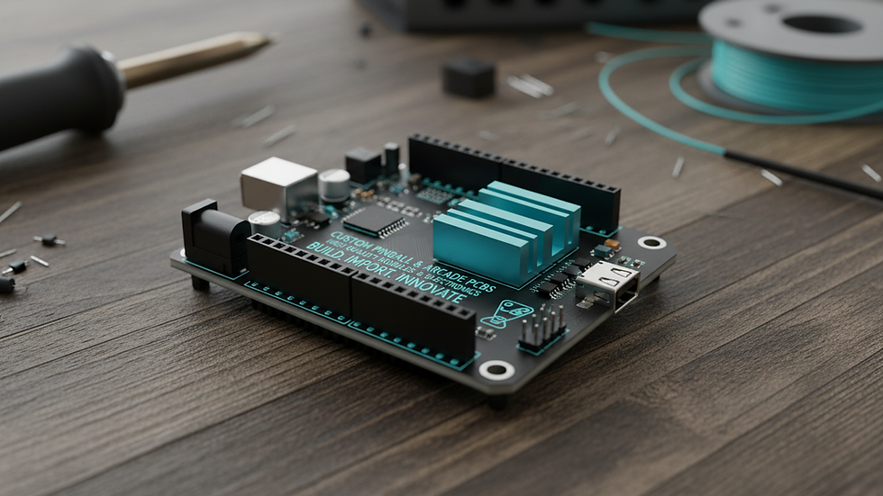
Suggested featured image: A PN532 NFC module beside NFC cards, an Arduino development board and a dark electronics workbench with cyan accents.
Publishing note: The code snippets are modular examples and require the stated integration steps. Test them with your exact stock module, library version and chosen development board before publishing them as tested, plug-and-play projects. The product specifications and voltage warning above are based on the Modula Industries product listing.
Modula Industries — Powering Electronics.


Comments